This time, we’re going to talk about Measure Amps On A Multimeter. There is a lot of information about How to Measure Current with a Multimeter? on the internet, of course. Social media are getting better and better quickly, which makes it easier for us to learn new things.
Measuring Resistors In Circuit and How to Measure Amps Using a Multimeter are also linked to information about Multimeter Tutorial. As for other things that need to be looked up, they are about Measuring DC amps with a digital multimeter and have something to do with Current Measurement Deutsch.
71 Interesting Facts Measure Amps On A Multimeter | How to Measure Amps with a Clamp meter-3 steps GUIDE
- Some multimeters also have a diode check function. A diode is like a one-way valve that only lets electricity flow in one direction. The exact function of the diode check can vary from multimeter to multimeter. If you’re working with a diode and can’t tell which way it goes in the circuit, or if you’re not sure the diode is working properly, the check feature can be quite handy. If your multimeter has a diode check function, read the manual to find out exactly how it works. - Source: Internet
- A typical multimeter should have Red and Black probes. During the configuration, ensure that the black probe is in the “COM” (common) socket. If you don’t see the label “COM” you should proceed to plug the black probe into the port labeled “Negative”. - Source: Internet
- Most multimeters (except for very inexpensive ones) have fuses to protect them from too much current. Fuses “burn out” if too much current flows through them; this stops electricity from flowing, and prevents damage to the rest of the multimeter. Some multimeters have different fuses, depending on whether you will be measuring high or low current, which determines where you plug the probes in. For example, the multimeter shown in Figure 5 has one fuse for 10 amps (10A) and one fuse for 200 milliamps (200mA). - Source: Internet
- First of all check capacity of your clamp ammeter for current testing. Set clamp meter on desired range of amps ac/dc present across selector nearby voltage symbol. You can remove testing leads if already connected because there is no need for leads in this test. - Source: Internet
- A clamp meter is the most appropriate tool for measuring amps. Clamp meters are easy to use and provide accurate readings of current flowing through a conductor. Choose a clamp meter that is appropriate for the job at hand and has the features you require. - Source: Internet
- Instructions for changing the fuse vary with each multimeter model, so you will need to check your multimeter’s manual for instructions. This tutorial from SparkFun provides directions for changing a fuse on their brand of multimeter, but remember that these directions might not apply to your model. Note that in some multimeters-especially in inexpensive ones-you might not be able to change the fuse. - Source: Internet
- One way to see if your 200 mA fuse has blown - is to disconnect the multimeter from everything, then turn off the multimeter, and open it up —— to remove the 200 mA fuse. And then visually inspect the fuse - to see if it has blown. Otherwise, you can use the multimeter to measure the resistance of that fuse —– to see if it has blown. - Source: Internet
- There are various ways of verifying this. First, you can plug the multimeter into a wall socket and check it with your volt meter. If the voltage is not there, then you know that the multimeter might not be working properly. - Source: Internet
- Advanced multimeters might have other functions, such as the ability to measure and identify other electrical components, like transistors or capacitors. Since not all multimeters have these features, we will not cover them in this tutorial. You can read your multimeter’s manual if you need to use these features. - Source: Internet
- Using a dedicated Frequency Counter is recommended when there is a need to measure high frequency signals and with higher accuracy. To measure frequency with a benchtop multimeter, set the multimeter to “FREQ” mode, then connect the positive probe to the “INPUT HI” port and the negative probe to the “INPUT LO” port. Ensure the circuit or device under test is powered on, then probe across the component to be measured for the frequency. - Source: Internet
- Some multimeters have a continuity check, resulting in a loud beep if two things are electrically connected. This is helpful if, for instance, you are building a circuit and connecting wires or soldering; the beep indicates everything is connected and nothing has come loose. You can also use it to make sure two things are not connected, to help prevent short circuits. - Source: Internet
- Test leads are flexible, insulated wires (red for positive, black for negative) that plug into the DMM. They serve as the conductor from the item being tested to the multimeter. The probe tips on each lead are used for testing circuits. - Source: Internet
- For getting rid from this risky process we use clamp meters to measure current. Clamp meters use electromagnetic fields to measure current around a conductor. That’s why we have to clamp on them around a cable with live load and they calculate amps value by sensing magnetic field around that cable. Normally we can measure ac current from 0.001 amperes to 1000 A. - Source: Internet
- The left image is a multimeter with no probes inserted. The center image is a multimeter that has a black probe inserted into the center port and a red probe inserted into the right-most port. This setup is rated to measure current under 200 milliamps. The right image shows a multimeter that has a black probe inserted into the center port and a red probe inserted into the left-most port. This setup is rated to measure current up to 10 amps. - Source: Internet
- It’s important to check the manual of your multimeter to see where it draws the line in terms of “low resistance” to sound the continuity buzz. This resistance is around 20-ohms for many multimeters. To test for continuity using a benchtop multimeter, set the multimeter to continuity mode by pressing the button that looks like it has a sound symbol. Connect the positive probe to the “INPUT HI” port, the negative probe to the “INPUT LO” port, and ensure the circuit or device under test is powered off. Probe various points on the circuit and listen for the continuity “beep”. - Source: Internet
- Place the multimeter leads into the circuit using a series configuration. The electricity must be redirected to flow completely through the multimeter to obtain an accurate reading. Current should usually move into the red lead and exit the black lead. - Source: Internet
- Deciding on the best multimeter can be a daunting task. The price ranges can vary widely by brand and features. Be sure to explore all considerations that must be factored in when choosing a benchtop multimeter. - Source: Internet
- (and power supply) with a higher-performance electro-meter, the most versatile and economical solution is to use a stable DC power supply and one of the new Truevolt multimeters from Keysight. These equipments have a low current range for measurements up to 1? A with a resolution of pA and a deviation of less than 100pA. Your - Source: Internet
- If your multimeter is not auto-ranging, you might need to adjust the range. If your multimeter’s screen just reads “0,” then the range you have selected is probably too high. If the screen reads “OVER,” “OL,” or “1” (these are different ways of saying “overload”), then the range you have selected is too low. If this happens, adjust your range up or down as necessary. Remember that you might need to consult your multimeter’s manual for specifics about your model. - Source: Internet
- Old circuit boards are constructed with a lead-based solder, which is toxic. Always wash your hands carefully after handling solder, and check your local waste disposal guidelines to see if there are special rules about disposing of lead as hazardous waste.) Set your multimeter to measure resistance, and have everyone in your house take turns grabbing the metal tips of the probes (one in each hand). Who has the highest resistance? The lowest? - Source: Internet
- Although they come with two probes, many multimeters have more than two places in which to plug the probes, which can cause some confusion. Exactly where you plug the probes in will depend on what you want to measure (voltage, current, resistance, continuity test, or diode test) and the type of multimeter you have. We have provided one example in the images below—and you can check our gallery for a multimeter similar to yours—but since all multimeters are slightly different, you might need to consult the manual for your multimeter. - Source: Internet
- AC current or alternating current is the measurement of current that periodically changes directions. The unit of measure for AC current is [amps, AC]. Like DC current measurements, AC current must be measured in series with the circuit to allow the electrons to flow through the multimeter in order to take the measurement. - Source: Internet
- Digital multimeters combine the testing capabilities of single-task meters—the voltmeter (for measuring volts), ammeter (amps) and ohmmeter (ohms). Often, they include several additional specialized features or advanced options. Technicians with specific needs, therefore, can seek out a model targeted to meet their needs. - Source: Internet
- Clamp meters are specially built to measure high value current, while most digital multimeters have a capacity of only 10 to 20 amps AC/DC. Clamp on ammeters also provides a more safe and easy to understand process for measuring current. So relatively for newbies and diy enthusiasts, clamp meters are a better choice for testing amperes. - Source: Internet
- Most people think of a multimeter as a device that measures voltage, resistance, and maybe even frequency. However, a multimeter has many more uses than that. You can also use it to measure amps (alternating current) or AC current. - Source: Internet
- Switch ON the multimeter and select the current function. In the multimeter in the first image above, the DC current function is on the right side of the dial. Select the lowest range (2000µ amperes for this multimeter) - Source: Internet
- You simply need to plug the leads of the clamp into the multimeter. Connect the other end of the clamp to the circuit. You will connect the clamp to the live wire. - Source: Internet
- The diode check feature is useful to determine in which direction electricity flows through a diode. The exact operation of the “diode check” function will vary for different multimeters, and some multimeters do not have a diode check feature at all. Because of this variety, and because the feature is not required for most Science Buddies projects, we have not included directions here. If you need to do a diode check, consult the manual for your multimeter. - Source: Internet
- Do you have anything you can take apart with a circuit board inside, like an old toy, or a TV remote? Use the continuity check on your multimeter (if it has one) to test which parts of the circuit are directly connected to each other. ( Warning: Old circuit boards are constructed with a lead-based solder, which is toxic. Always wash your hands carefully after handling solder, and check your local waste disposal guidelines to see if there are special rules about disposing of lead as hazardous waste.) - Source: Internet
- Do you have a multimeter but are confused about how to use it or are getting unexpected readings? If so, the sections below will help you sort through what to do. If there are words or concepts you do not understand, or symbols on your multimeter that puzzle you, return to the Multimeter Overview tab. If you are looking for multimeter usage ideas or labeled photographs of assorted multimeter models, then visit the other tabs in this multimeter tutorial. - Source: Internet
- You will probably need to open up your multimeter to access the fuses (Important: Always disconnect the probes before you do this). Some multimeters have covers that will pop or slide off, and some have screws that must be removed first. Fuses usually look like small, glass cylinders with metal caps on the end and a thin wire running down the middle: - Source: Internet
- To perform a diode test using a benchtop multimeter, set the multimeter to the diode test mode by pressing the button with the diode symbol. Connect the positive probe to the “INPUT HI” port, and the negative probe to the “INPUT LO” port. Ensure the circuit or device under test is powered off. Apply the probes across the diode (making sure to ensure proper polarity), then record the diode drop voltage. - Source: Internet
- Don’t forget to check clamp on meter battery, it should be in stable condition. Always set multimeter on the highest available range for better results and to avoid any misfortune. Suppose if you are testing a current value in between 20 to 40 amps, clamp meter should set at least at 200 A. - Source: Internet
- To measure DC amps with a clamp meter, first, ensure that the clamp’s jaws are wrapped around the wire through which the current is flowing. Select the appropriate measurement range for the expected amount of current on the clamp meter. Finally, take note of the display reading. - Source: Internet
- A multimeter is a device that can measure several key details of an electrical circuit. These units are commonly used by professional electricians as well as hobbyists, and they can be purchased from retail stores such as Radio Shack. A modern digital multimeter makes it easy to measure the current flow, expressed in amps; voltage can also be determined. Once the voltage and current are known, you can calculate watts using a simple formula. - Source: Internet
- A clamp meteris used to measure the flow of electricity through a circuit without touching the wires directly. People who work on electrical systems often use clamp meters. A clamp meter measures current by clamping its jaws around a wire. Many clamp meters have parts that can also measure voltage and resistance. A clamp meter is the most accurate way to figure out how many amps are in a circuit. - Source: Internet
- Measuring AC voltage is almost identical to measuring DC voltage, however this mode is used for measuring the voltage potential between two points of an AC or “alternating current” circuit. The unit of measure for AC voltage is [volts, AC]. To measure AC voltage using a benchtop multimeter, select the “AC V” mode and connect your probes. The positive probe should be connected to the “INPUT HI” port, while the negative probe should be connected to the “INPUT LO” port. Apply power to the circuit or device under test and probe points on circuit - Source: Internet
- Let’s start with DC voltage, one of the simplest and most-used multimeter measurements. The DC voltage measurement is used to determine the difference in electrical potential between two points in a DC or “direct current” circuit. That difference in potential is measured in units of [volts, DC]. To measure DC voltage using a benchtop multimeter, once you’ve turned it on, select “DC V” mode. - Source: Internet
- The same value might appear differently when measured with a different scale selected on the multimeter dial. For an example, let’s use measuring the DC voltage from a AA battery—which we expect to be 1.5V—using a multimeter that has settings for 200mV, 2V, 20V, 200V, and 600V. When measuring the battery with each setting, we get these readings: - Source: Internet
- A multimeter is an indispensable tool for most engineers and technicians when measuring current or voltage. However, when there is a need to measure the power consumption of a device, most multimeters often do not meet the necessary requirements: work at a high sampling rate, sufficient measuring ranges of current, or a quick data transfer to the PC for further analysis. Keysight Technologies’ 34465A/34470A multimeters provide, in addition to measurements of current, voltage, frequency, period, temperature, etc., measurement ranges of current and sampling rate ideal for consumption measurement. - Source: Internet
- DC current or direct current measures the one-directional flow of electrons in a circuit, and the unit of measure is [amps, DC]. In order to make any current measurement, there must be an ‘open’ in the circuit that is then closed by the multimeter, thus allowing the current to flow through the multimeter itself. To state another way, measuring current must be done in series with the circuit; whereas voltage and resistance measurements are done in parallel with the circuit. - Source: Internet
- To take a 2-wire resistance measurement with a benchtop multimeter, select the “ohm” or “Ω” mode, and connect the probes to the “INPUT HI” and “INPUT LO” ports. Ensure the circuit or device under test is powered off. Then probe the desired area of the circuit. - Source: Internet
- Figure 4. A typical pair of multimeter probes. A typical pair of multimeter probes. - Source: Internet
- You might have noticed some other symbols besides V, A, Ω, and metric prefixes on the front of your multimeter. We’ll explain some of those symbols here, but remember, all multimeters are different, so we cannot cover every possible option in this tutorial. Check your multimeter’s manual if you still can’t figure out what one of the symbols means. You can also browse our multimeter gallery to see labeled pictures of different multimeters. - Source: Internet
- Dynamic current measurements can be quite complex because a range change of the DMM is necessary based on the current level being measured. Keysight has specialized instruments (such as the SMU N6782A) that can simultaneously digitize power, voltage and current without range problems. While this may be a great solution for certain current characterization applications, the option of using a Truevolt multimeter is much more economical. A visual example: this figure describes the discharge of a battery, with a dynamic range of measurement automatically adjusted with the auto ranging function. - Source: Internet
- This is the basic process how you measure current using a multimeter. The idea is to keep the test probes between the two leads of a load. In our case, the load was the LED bulb so we pointed one probe at the anode and the other at the opposite side. - Source: Internet
- Insert the leads into the multimeter connections labeled “current.” Typically, the black lead should be connected to the “common” port, while the red lead is connected to a port that matches the selected current range. This arrangement varies, depending on the unit. Consult the multimeter labels carefully to confirm that the configuration is correct for measuring current. - Source: Internet
- Direct current (abbreviated DC) is current that always flows in one direction. Direct current is supplied by everyday batteries—like AA and AAA batteries—or the one in your cell phone. Most of the Science Buddies projects you do will probably involve measuring direct current. Different multimeters have different symbols for measuring direct current (and the corresponding voltage), usually “DCA” and “DCV,” or “A” and “V” with a straight bar above or next to them. See “What do all the symbols on the front of the multimeter mean?” for more information about the abbreviations and symbols on multimeters. - Source: Internet
- Diode Test - Multimeters can also be used to measure the diode drop across a forward-biased diode. To measure the diode voltage drop, the multimeter automatically applies a small voltage across the probes and increases this voltage until the two probes are electrically connected (i.e. the diode is conducting and forward-biased). The unit of measure for the diode test is [volts, dc]. - Source: Internet
- Below you can learn a smart method of 3 steps on the topic “how to measure amps with a clamp meter”. Amp is a basic unit of current that defines amount of current passing from a particular point in any device or circuit. Clamp meters are specially built for testing current values in a safer way. - Source: Internet
- Remember, this gallery is meant to be a general guide; if you do not see your model of multimeter pictured here, your best bet is to consult your specific multimeter’s manual. If you need help getting introduced to multimeters in general, refer back to our Multimeter Overview section. If you need to know how to take a specific type of measurement, refer to the Using a Multimeter section. - Source: Internet
- This meter has a separate jack for measuring voltage and resistance. And two jacks for different ranges of current measurement. One current measurement jack is safe for currents up to 200mA. The other can be used to measure currents up to 20 amps. - Source: Internet
- To get started, you should first try to familiarize yourself with a multimeter. Most digital multimeters tend to have the same appearance. They are usually black, and rectangular, and have a screen, buttons, and a probe. - Source: Internet
- Figure 3. The multimeter on the left is manual-ranging, with many different options (indicated by metric prefixes) for measuring different amounts of voltage, current, and resistance. The multimeter on the right is auto-ranging (note how it has fewer options for the selection knob), meaning it will automatically select the appropriate range. The multimeter on the left is manual-ranging, with many different options (indicated by metric prefixes) for measuring different amounts of voltage, current, and resistance. The multimeter on the right is auto-ranging (note how it has fewer options for the selection knob), meaning it will automatically select the appropriate range. - Source: Internet
- To measure the current through a lightbulb the multimeter becomes part of the circuit and transfers electricity from the battery to the lightbulb. The positive probe of the multimeter (red) is connected to the positive side of a battery while the negative probe of the multimeter (black) is connected to one lead of a lightbulb. The free lightbulb lead is then connected to the negative side of the battery using wire. Current will flow from the battery to the multimeter and then into the lightbulb. - Source: Internet
- use a multimeter to test electricity from the wall outlets in your home. Electricity from wall outlets is very dangerous and can be fatal. Do not connect the probes directly to a battery or other power supply when you have a “current” measurement setting selected. This will cause a “short circuit” across the battery terminals, and a very high current will flow through your multimeter. This will probably blow a fuse, or possibly damage the multimeter. - Source: Internet
- To measure DC current with a benchtop multimeter, select the “I DC” mode on the multimeter. Connect the positive probe to the “mA” port for measuring small currents or the “10A” port for measuring large currents. Connect the negative probe to the “INPUT LO” port. Apply the probes to the appropriate points in series with the circuit, then apply power to the circuit or device under test and record the DC current measurement. - Source: Internet
- To make a 4-wire resistance measurement with a benchtop multimeter, select the “ohm” or “Ω” mode on your multimeter (you may have to press this button more than once to ensure 4-wire mode is selected). Connect the first set of probes to the “INPUT HI” and “INPUT LO” ports, and the second set of probes to the “SENSE HI” and “SENSE LO” ports. Ensure the circuit or device under test is powered off, then probe the desired area of the circuit using both “HI” probes on one side of the component, and both “LO” probes on the other side of the component being measured - Source: Internet
- Measuring resistance with a multimeter can be done a couple of different ways, depending on the level of accuracy needed in the measurement. Multimeters measure resistance by injecting a small current into the circuit, and then measuring the voltage drop across those points in the circuit. The known current, and the resulting voltage drop are then used to calculate the resistance using Ohm’s Law, V=I^2*R. Since even wires have resistance, the wires of the probes can actually add to the observed resistance measurement. For this reason, there are two different modes for measuring resistance: 2-wire mode and 4-wire mode. - Source: Internet
- You might be confused by all the symbols on the front of your multimeter, especially if you don’t actually see words like “voltage,” “current,” and “resistance” spelled out anywhere. Don’t worry! Remember from the “What are voltage, current, and resistance?” section that voltage, current, and resistance have units of volts, amps, and ohms, which are represented by V, A, and Ω respectively. Most multimeters use these abbreviations instead of spelling out words. Your multimeter might have some other symbols, which we will discuss below. - Source: Internet
- -Turn off the power supply to the circuit: You can only find out the amperage by connecting the multimeter to the circuit. In other words, it should be part of the circuit. So, you should start by turning off the power supply and disconnecting the positive cable from the power source. - Source: Internet
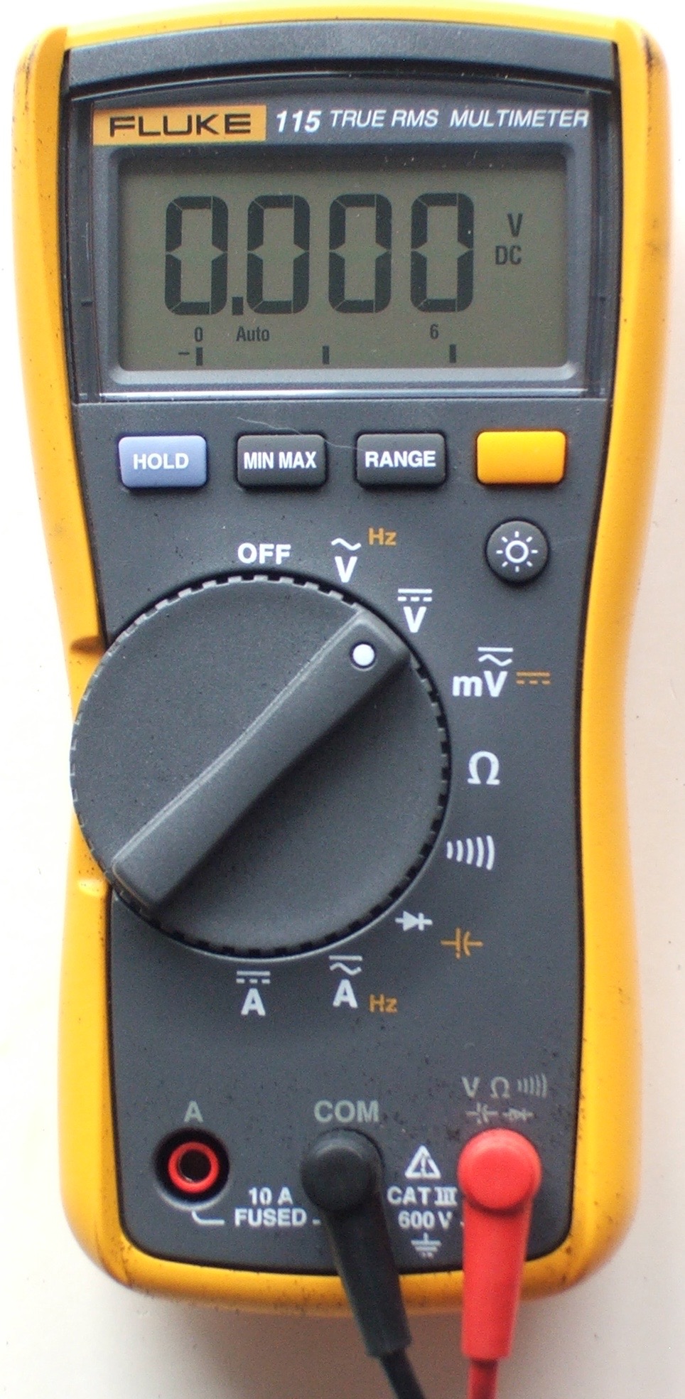
- A multimeter is a handy tool that you use to measure electricity, just like you would use a ruler to measure distance, a stopwatch to measure time, or a scale to measure weight. The neat thing about a multimeter is that unlike a ruler, watch, or scale, it can measure different things — kind of like a multi-tool. Most multimeters have a knob on the front that lets you select what you want to measure. Below is a picture of a typical multimeter. There are many different multimeter models; visit the multimeter gallery for labeled pictures of additional models. - Source: Internet
- Hook the multimeter leads up to a speaker using speaker wire, and set the multimeter to measure AC amps (or AC volts if AC amps is not available). Who can get the multimeter to display the biggest number by yelling into the speaker? (In this case, the speaker is working like a microphone, generating current when it detects sound.) - Source: Internet
- Your multimeter probably came with red and black wires that look something like the ones in Figure 4. These wires are called probes or leads (pronounced “leeds”). One end of the lead is called a banana jack; this end plugs into your multimeter (Note: some multimeters have pin jacks, which are smaller than banana jacks; if you need to buy replacement probes, be sure to check your multimeter’s manual to find out which kind you need). The other end is called the probe tip; this is the end you use to test your circuit. Following standard electronics convention, the red probe is used for positive, and the black probe is used for negative. - Source: Internet
- To measure AC current with a benchtop multimeter, select the “I AC” mode, connect the positive probe to the “mA” port for measuring small currents, or the “10A” port for measuring large currents. Connect the negative probe to the “INPUT LO” port. Apply the probes to the appropriate points in series with the circuit, then apply power to the circuit or device under test. - Source: Internet
- Multimeters can also be used to measure frequency of an AC voltage signal. Frequency is a measurement of the number of cycles repeating on a signal every second. For example, a sine wave that repeats 10 cycles every second would have a frequency of 10 Hertz or Hz. The input frequency range on multimeters can vary greatly, so be sure to verify that your multimeter is capable of measuring higher frequency signals. Like voltage, the frequency measurement is done in parallel to the circuit. - Source: Internet
- Select the “Current” setting on the main dial of the multimeter. Choose a current range high enough for the circuit being tested. For example, if the circuit has a current that you estimate to be around five amps, select the “10 amp” setting instead of the “1 amp” option. Choosing a setting that is too low can overload the multimeter. - Source: Internet
- Measuring continuity (or electrical connectedness) with a multimeter is an extremely useful debugging and trouble-shooting tool. When a circuit is not working as expected, one of the first actions in finding the issue is to check to make sure all the expected connections are there and that there are no unwanted electrical shorts. Of course one could use the resistance measurement mode of the multimeter to check these connections are present, but using the continuity mode makes it even easier. This is because the multimeter will give you an audible beep, if there is a low resistance connection between the probes, so you don’t even have to look up from the circuit you’re debugging. - Source: Internet
- Most multimeters also use metric prefixes. Metric prefixes work the same way with units of electricity as they do with other units you might be more familiar with, like distance and mass. For example, you probably know that a meter is a unit of distance, a kilometer is one thousand meters, and a millimeter is one thousandth of a meter. The same applies to milligrams, grams, and kilograms for mass. Here are the common metric prefixes you will find on most multimeters (for a complete list, see the References tab): - Source: Internet
- The configuration process may also include setting the multimeter’s range. This ensures that you get an accurate reading. The range you should set depends on the type of circuit you are measuring the amps for. For example, a range of 10 amps is ideal for measuring a 12-volt battery. - Source: Internet
- Measuring current is one of the most common measurements electronic engineers make to verify that a circuit or device is working as intended. There are a number of methods you can use to measure current, but the simplest way to measure direct current (DC) is by using a digital multimeter A gap is made in the circuit and is connected to a digital multimeter (DMM) so that it becomes part of the circuit itself. The current passes through the DMM, which displays the measurement on the display screen. - Source: Internet

Here are a few tips to help you find information about Multimeter Measure Voltage:
- Look for good places to get information about How to Measure Amps or Watts With a Multimeter. This can be done in libraries, on websites, or even by paid journalists.
- When looking for information about How To Measure Current With Multimeter, it’s important to know that there are different kinds of online sources, like Google and YouTube. Social media sites like Facebook and Twitter are also good places to look for information about How to Measure Amps or Watts With a Multimeter.
Video | Measure Amps On A Multimeter
To get the best information about test amps on multimeter, you should read to find out how true each source is.
This article has a few videos from different places about How to Measure Amps Using a Multimeter that will help you learn more about it. The Internet is a great place to find out about a wide range of things.
## Here are some crucial aspects concerning how to measure amps on a digital multimeter:- Measure Amps On A Multimeter
- Measuring Amps On A Multimeter
- Measuring Current On A Multimeter
- How Do You Measure Amps On A Multimeter
- Test Amps On Multimeter

With so many websites and forums that talk about How To Read Multimeter Amps, it shouldn’t be hard to find what you need.
Most people are used to getting information about Measuring Resistors In Circuit in a very different way than this. It lets you look at the information about how to measure amps on a digital multimeter and how it can be used in more detail.
 ways to put information about How to Measure Current with a Multimeter? in a way that looks good and is useful. They can be used in business and marketing, and they can also be used to talk about How to Measure Amps with a Multimeter. So, we also give you some pictures about Multimeter Measure Voltage.
In the end, this article gives a summary of How To Measure Voltage With A Multimeter. Also talked about are measure amps battery multimeter and Multimeter Basics, which you can use to compare how much you know about measure amps dc multimeter.
